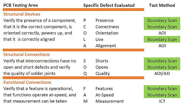
 Boundary Scan is a method of testing electronic assemblies, primarily but not limited to assemblies with a high degree of digital components. The only technical requirement is the existence of at least one component with an interface according to JTAG IEEE 1149.1. The assumption that only components that have such an interface is not true. It is important to have access to non-JTAG components through a JTAG-capable device. Even analog components can be tested if the design has been carefully planned and designed for testability.
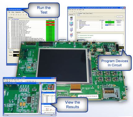
Corelis ScanExpress consists of a number of software components used to generate, execute and analyse test plans based on JTAG/Boundary Scan. All software components run in Windows 7, 8, 8.1 or Windows 10.
Typically, the unit under test (UUT) is connected to the PC running ScanExpress through a JTAG controller, available in a variety of form factors. For development of test plans, verification of prototype hardware and desktop use, a USB-connected JTAG controller with a single TAP (Test Access Port) will be a good choice. In a production line, a PCIe, LAN or USB based multi-TAP controller may be the best option. Some of the available JTAG controllers easily integrate into National Instruments test systems under LabView.
If you want to learn more about Boundary Scan or, how to integrate Boundary Scan into an ICT system or, about possibilities and limitations of this fascinating technology, please contact us. We have used Boundary Scan successfully for many years in our own and customer projects. Our experience enables us to assess whether or nor Boundary Scan is a useful option for your testing needs.
Design for Test (Testability)
To analyse the testabilty, especially during development, ScanExpress DFT (Design for Test, P/N Nr. 20300) is very useful. ScanExpress DFT gives the designer hints how to modify the design in order to improve test coverage. Design errors can be detected at an early stage, potentially reducing the number of design spins.
Generation of Test Plans
The generation of test patterns used to execute boundary scan tests is accomplished with ScanExpress TPG (Test Pattern Generator, P/N. 20400). Boundary Scan typically cannot be used to test hardware at speed. That is because pins of a device with a JTAG port are actuated via the so-called scan-chain which inherently does not have the timing of the device under test. There is an interesting article that explains the concept of JTAG/Boundary Scan technology.
However, Corelis has a Boundary Scan extension that remedies the problem of the basic Boundary Scan test method: ScanExpress JET can be used to comfortably test Ethernet, CAN, UART or USB interfaces at speed. Furthermore, SDRAM (DDR, DDR2, DDR3, DDR4) can be tested at system speed, while flash devices, serial flash, EEPROMs and CPLDs can be programmed from within the test procedure. The list of devices supported by JET is constantly being expanded.
Testing multiple Boards
If a combination of boards designed separately requires Boundary Scan testing, ScanExpress Merge (P/N 20196) is required. ScanExpress Merge merges net and component data into a single set of files that can be used by TPG to create test files. ScanExpress Merge is also helpful if a board is tested in combination with a test fixture that also contains JTAG/Boundary Scan capable devices.
Test Execution and Analysis
ScanExpress Runner (P/N 20650) is the central software component used to execute test plans generated with the tools described above. ScanExpress ADO (Advanced Diagnostic Option, P/N 20210) and ScanExpress Viewer (P/N 20315) are add-ons to Runner that generate concise test reports and visualize results. ADO and Viewer are especially helpful when tests are carried out by someone who has little or no background knowledge of the boards being tested, e.g. assembly line personnel.
Testing and Programming I²C and SPI Components
SPI or I²C devices can be tested and programmed even without being connected to a Boundary Scan device if connected to a set of special pins available on the TAP (test access port) of all Corelis JTAG controllers. ScanExpress Programmer JTAG (P/N 20603) and ScanExpress Programmer SPI/I2C (P/N 20601) are the software components used for that purpose.
Interactive Debugger
An interactive Debugger (ScanExpress Debugger, P/N 20409) can be used to analyse problematic circuitry using a C-like script language. There is an interesting video explaining the capabilities of this excellent tool.
JTAG Embedded Test (JET)
ScanExpress JET greatly enhances automatic circuit board testing by extending boundary-scan structural test coverage to virtually every signal on the board that is accessible by an on-board CPU, DSP or microcontroller. ScanExpress JET utilizes proprietary “JTAG Embedded Test” (JET) technology, which uses a processor’s JTAG debug port to download and control native processor code to perform at-speed functional testing of the UUT. JET seamlessly integrates with traditional boundary-scan testing. When running tests using ScanExpress, JET becomes virtually invisible other than it significantly accelerates the test procedure.
Read more about JET.
Integration von ICT und Boundary-Scan
ScanExpress can easily be integrated with traditional ICT systems (Bed-of-Nails, Flying Probes) provided by a number of manufacturers such as SPEA, Takaya, Agilent, Checksum, SEICA, Teradyne and others. Combining Boundary Scan and ICT yields the best possible test coverage while minimizing development efforts and investments.
Boundary Scan Application Support
Corelis and local resellers provide education and hands-on support during all phases of your Boundary Scan projects. Individual support is available on request, e.g. if you need to assess and optimize the test coverage of a board design in progress. Please, do not hesitate to contact us by phone (+49-211-2714630) or using our contact form.
More Information on ScanExpress Boundary Scan tools can be found at the Corelis Website.
Corelis offers an extensive line of ScanExpress software modules that can be custom tailored to create the right boundary-scan package for any user. Corelis’ ScanExpress software is compatible with Microsoft Windows 7, Windows 8/8.1, Windows 10 and 11 as well as all of Corelis’ hardware platforms. Furthermore, DLLs of these functions for integration National Instruments' LabView, LabWindows/CVI, TestStand, Geotest ATEasy, Agilent's VEE, Visual Basic and C++ are available.
ScanExpress software version 10.2.0 is now available to all users with a current maintenance contract and with new software purchases. Release notes for this version are found further down this page.
ScanExpress Software Components for Testing Electronic Assemblies using Boundary-Scan
 ScanExpress TPG™ is an intelligent test pattern generator that enhances the process of boundary-scan automation at an exceptional level of ease of use. ScanExpress TPG automatically generates test patterns that facilitate pin-level fault detection and isolation of all boundary-scan testable nets on a printed circuit board (PCB). ScanExpress TPG also creates test vectors to detect faults on pins of non-JTAG components such as clusters and memories that are accessible by IEEE-1149.1 compatible devices.
 ScanExpress JET™ represents state-of-the-art in automatic circuit board testing by extending boundary-scan structural test coverage to virtually every signal on the board that is accessible by an on-board CPU. ScanExpress JET utilizes proprietary “JTAG Embedded Test” (JET) technology, which uses a processor’s JTAG debug port to download and control native processor code to perform at-speed functional testing of the UUT.
 ScanExpress DFT™ Analyzer is able to accurately calculate the test coverage of boards and systems that include a mix of both boundary-scan and non-boundary-scan devices. The software additionally helps development engineers detect low coverage areas on their designs allowing them to make decisions on increasing fault coverage before the board is sent for layout.
Test Execution System
 ScanExpress Runner™ provides a runtime executive environment that is friendly for design, production, and field service. ScanExpress Runner allows users to execute a test sequence or individual test steps based on test patterns generated with ScanExpress TPG and/or ScanExpress JET. To identify failures - if any - a truth table diagnostic display is generated for further inspection.
 ScanExpress Runner Gang™ is the workhorse software piece to perform parallel gang testing and In-System Programming of CPLDs and Flash devices. This solution is fully concurrent and allows simultaneous testing of multiple boards using a single PC and a single operator. ScanExpress Runner Gang addresses high-throughput boundary-scan applications including high-volume production.
 ScanExpress Viewer™ is a powerful graphical fault identification system that helps to isolate the source and location of faults encountered during boundary-scan test of printed circuit board assemblies. The device and pin location capabilities provide test operators the immediate board location of the faulty pin or net.
ScanExpress ADO™ is an add-on option for the ScanExpress Runner and ScanExpress Runner Gang execution environments. The Advanced Diagnostics Option automates test vector analysis by intelligently deciphering standard truth table diagnostic information and presenting specific fault information to the user in a detailed verbose format.
 ScanExpress Merge™ makes system-level boundary-scan test development a snap by automatically combining multiple target assemblies into a single boundary-scan compatible target system. The tool provides automatic handling for each board netlist, scan-chain, and interconnect information.
 ScanExpress JTAG Debugger™ provides a simple, stand-alone environment for complete pin control over any boundary-scan device. The interactive graphical user interface lets users mimic the functionality of a logic analyzer by observing all boundary-scan controllable inputs while also providing the capability to drive output pins to specific logic states. The software can be used to quickly apply patterns to specific areas of a board giving immediate feedback when faults are detected.
Boundary-Scan In-System Programming (ISP) Tools
 ScanExpress JTAG Programmer™ is a universal in-circuit programming tool that can program and verify Flash memories, serial EEPROMs, CPLDs, FPGAs, and other programmable logic devices. Programming methods include JTAG, I2C, SPI, and Target Assisted. The extensive device library includes chip manufacturers such as Altera, Cypress, Micron, Spansion, Intel, Microchip, ST Microelectronics, Texas Instruments, Xilinx, and many more.
 The ScanExpress Flash Generator™ creates a Board File, which is used to provide ScanExpress Programmer (or other compatible applications) with the necessary information to program a given target board configuration. ScanExpress Flash Generator can be used as a standalone utility or as a module integrated with the ScanExpress TPG environment.
ScanExpress Version 9.4.x Release Notes
Corelis ScanExpress applications have been updated with the latest features, enhancements, and device support.
ScanExpress Runner now includes an asynchronous API for integration with third party applications. The asynchronous execution functions allow applications to integrate ScanExpress Runner functionality without having to wait for execution to finish—applications can now begin execution and then poll to determine current status or abort the current execution.
The new functions are:
AsyncAbort() Aborts asynchronous Test Plan execution.
AsyncGetStatus() Retrieves the current status and completion percentage of asynchronous Test Plan execution.
AsyncRunTestPlan() Runs the currently loaded Test Plan asynchronously, returning immediately.
ScanExpress Runner Diagnostic & Logging Improvements
ScanExpress Runner now includes full test plan and test step path information in the test log file for improved traceability. Additionally, flash manufacturer and device ID information will now be included in diagnostics and test logs when Device ID tests pass. Finally, we’ve improved JAM/STAPL diagnostics to include additional checksum data when available.
ScanExpress Runner Gang USB-1149.1/4E
ScanExpress Runner Gang can now utilize USB-1149.1/4E and QuadTAP/CFM hardware for concurrent test execution. Gang (concurrent) tests on up to 4 TAPs can now be run on the benchtop with USB-1149.1/4E hardware or integrated into Teradyne testers with the QuadTAP/CFM and expander cards.
ScanExpress JET CPU Support & Improvements
ScanExpress JET supports many microcontrollers, FPGAs, and SoCs, e.g. Infineon's Aurix, Nvidia's Tegra K1, NXP's CorIQ P2, Xilinx Zynq, and Mobileye's EyeQ3 devices. Starting with version 9.4 ScanExpress JET supports Marvell OCTEON III CN7200 Multi-Core MIPS64 Processors and Texas Instruments TMS320C6748 DSP Processors. Each new processor support package includes base RAM and NOR flash tests and programming support. Please contact Corelis Sales for pricing and availability. Additionally, Ethernet loopback tests are now included for NXP i.MX6 Applications Processors.
Corelis ScanExpress 9.4 is now available free for customers under maintenance. Please, inquire for more information.
JTAG Controllers for Board Level Testing
A wide selection of JTAG (boundary-scan) hardware controllers is available from Corelis, including PCI, PCI Express, USB 2.0, Ethernet/LAN, PXI/cPCI and VXI, with price and performance to meet your specific requirements. For performance critical JTAG applications, Corelis offers boundary-scan controllers that operate at up to 100MHz sustained TCK frequency, enabling fast board JTAG interconnect testing and JTAG programming of flash memories at their maximum theoretical speed. From single-TAP JTAG-controllers for development and test bench use to multi-TAP controllers for inline volume production testing, there is a suitable controller for every purpose.
Corelis offers support for a variety of devices and instruments from third-parties in an effort to provide existing test platforms comprehensive JTAG test execution with Corelis ScanExpress software products. Supported instruments include National Instruments PXI-655x HSDIO and Teradyne Di-Series modules. Corelis also provides support for JTAG testing with FTDI FT2232 ICs embedded on a unit under test (UUT).
For more information on JTAG technology, please check out the JTAG tutorial. You may also be interested in how to debug a dead board.
Analysers / Exercisers for I²C and SMBus
The high performance CAS-1000 I2C/E I2C/SMBus bus analyzer and exerciser is an enhanced model targeted towards IC verification and parametric testing in I²C and SMBus topologies. The CAS-1000-I2C/E hardware provides more advanced features such as master and slave emulation, bus specification validation, bus parameter measurement, glitch injection, clock stretching, and adjustable timing skew. In conjunction with Corelis ScanExpress software, the CAS-1000 controller can be used for Boundary Scan testing of complete boards as well as for (interconnect test, etc.) as well as for in-system-programming of Flash memory and CPLDs.
More information on Corelis Boundary Scan products, consulting and training is available on request.
Note: If in doubt which products or product combination suits your testing and programming needs, please, feel free to contact us or our European representatives.
 Other Benefits of JTAG Boundary-Scan Testing


 Boundary Scan is a method of testing electronic assemblies, primarily but not limited to assemblies with a high degree of digital components. The only technical requirement is the existence of at least one component with an interface according to
  ScanExpress TPG™ is an intelligent test pattern generator that enhances the process of boundary-scan automation at an exceptional level of ease of use. ScanExpress TPG automatically generates test patterns that facilitate pin-level fault detection and isolation of all boundary-scan testable nets on a printed circuit board (PCB). ScanExpress TPG also creates test vectors to detect faults on pins of non-JTAG components such as clusters and memories that are accessible by IEEE-1149.1 compatible devices.
 ScanExpress JET™ represents state-of-the-art in automatic circuit board testing by extending boundary-scan structural test coverage to virtually every signal on the board that is accessible by an on-board CPU. ScanExpress JET utilizes proprietary “JTAG Embedded Test” (JET) technology, which uses a processor’s JTAG debug port to download and control native processor code to perform at-speed functional testing of the UUT.
 ScanExpress DFT™ Analyzer is able to accurately calculate the test coverage of boards and systems that include a mix of both boundary-scan and non-boundary-scan devices. The software additionally helps development engineers detect low coverage areas on their designs allowing them to make decisions on increasing fault coverage before the board is sent for layout.
 ScanExpress Runner™ provides a runtime executive environment that is friendly for design, production, and field service. ScanExpress Runner allows users to execute a test sequence or individual test steps based on test patterns generated with ScanExpress TPG and/or ScanExpress JET. To identify failures - if any - a truth table diagnostic display is generated for further inspection.
 ScanExpress Runner Gang™ is the workhorse software piece to perform parallel gang testing and In-System Programming of CPLDs and Flash devices. This solution is fully concurrent and allows simultaneous testing of multiple boards using a single PC and a single operator. ScanExpress Runner Gang addresses high-throughput boundary-scan applications including high-volume production.
 ScanExpress Merge™ makes system-level boundary-scan test development a snap by automatically combining multiple target assemblies into a single boundary-scan compatible target system. The tool provides automatic handling for each board netlist, scan-chain, and interconnect information.
 ScanExpress JTAG Debugger™ provides a simple, stand-alone environment for complete pin control over any boundary-scan device. The interactive graphical user interface lets users mimic the functionality of a logic analyzer by observing all boundary-scan controllable inputs while also providing the capability to drive output pins to specific logic states. The software can be used to quickly apply patterns to specific areas of a board giving immediate feedback when faults are detected.
 ScanExpress JTAG Programmer™ is a universal in-circuit programming tool that can program and verify Flash memories, serial EEPROMs, CPLDs, FPGAs, and other programmable logic devices. Programming methods include JTAG, I2C, SPI, and Target Assisted. The extensive device library includes chip manufacturers such as Altera, Cypress, Micron, Spansion, Intel, Microchip, ST Microelectronics, Texas Instruments, Xilinx, and many more.
 The ScanExpress Flash Generator™ creates a Board File, which is used to provide ScanExpress Programmer (or other compatible applications) with the necessary information to program a given target board configuration. ScanExpress Flash Generator can be used as a standalone utility or as a module integrated with the ScanExpress TPG environment.